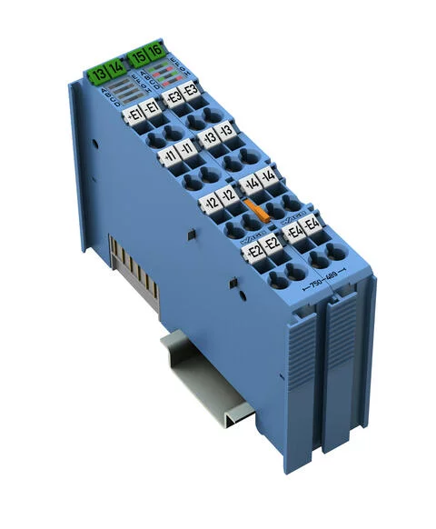
750-489 - 4-channel analog input; RTD/TC/Strain Gauge; 16 bits; Diagnostics; Intrinsically safe
- Brand: Wago
- Product Code: 750-489
Notes
Note | The analog output module must only be operated via 24 VDC Ex i! General information (e.g., installation regulations) on explosion protection is available in the WAGO I/O System 750 manuals! |
Technical data
Number of analog inputs | 4 |
Number of Channels | 4 |
Signal type | Resistive temperature device Resistors Potentiometer positions Thermocouple mV encoder |
Signal type (configurable) | yes |
Sensor connection | 4 x (2-wire); RTD/R: 3-wire; 4-wire |
Data width | 4 x 16-bit data; 4 x 8-bit control/status (optional) |
Resolution (over entire range) | 0.1 K of full scale value; 0.01 K of full scale value (restricted to -50 °C … +150 °C) |
Conversion time | ≥10 ms/2 wires (per channel)*; ≥20 ms/3 wires, 4 wires (per channel)*; *for RTD/R; TC/U conversion time depends on module setting |
Measurement error (25 °C) | In delivery state: ±0.2 % of the upper-range value (value achieved during calibration in operating environment 0 ≤ TA ≤ 55 °C); After user calibration: ±0.05 % of the upper-range value (only valid in the thermally stable operating state) |
Temperature coefficient | ±0.001 %/K of the upper-range value |
Intrinsic safety Ex i | yes |
Measurement range | Resistive temperature devices: Pt100, Pt200, Pt500, Pt1000, Ni100, Ni120, Ni200, Ni500, Ni1000, Ni1000-TK5000; Resistors: 250 Ω, 500 Ω, 1 kΩ, 2 kΩ, 4 kΩ, PTC; Potentiometer setting: 0 … 100 %; Thermocouples: Type B (+250 … +1,820 °C); Type C (0 … +2,315 °C); Type E (-200 … +1,000 °C); Type J (-210 … +1,200 °C); Type K (-200 … +1,372 °C); Type N (-200 … +1,300 °C); Type R, S (-50 … +1,768 °C); Type T (-200 … +400 °C); mV sensors: ±30 mV; ±60 mV; ±120 mV; ±250 mV; ±500 mV; ±1,000 mV; ±2,000 mV; Thermistor: PTC; Resistor bridges (strain gauges): Uref: 2.4 V; Ud: ±15 mV, ±30 mV, ±60 mV |
Cold junction compensation | integrated |
Supply voltage (system) | 5 VDC; via data contacts |
Current consumption (5 V system supply) | 60 |
Supply voltage (field) | 24 VDC; (Ex i power supply: UO = max. 27.3 V); via power jumper contacts (power supply via blade contact; transmission via spring contact) |
Current consumption, field supply (module with no external load) | 120 |
Power loss Pl | 1.6 W |
Isolation | Per EN/IEC 60079-11: 300 VAC system/supply; per EN/UL 61010-2-201: 1200 VDC system/supply/channel |
Number of incoming power jumper contacts | 2 |
Number of outgoing power jumper contacts | 2 |
Marking | ATEX/IECEx: II 3 (1) G Ex ec [ia Ga] IIC T4 Gc; II (1) D [Ex ia Da] IIIC; I (M1) [Ex ia Ma] I |
Explosion protection
Ex standard | EN IEC 60079-0, -7, -11 |
Safety-relevant data (circuit) | Uo = 4 V; Io = 13.46 mA; Po = 13.46 mW; linear characteristic curve |
Reactances Ex ia IIC | Lo = 0.19 H; Co = 100 µF |
Reactances Ex ia IIB | Lo = 0.78 H; Co = 1000 µF |
Reactances Ex ia IIA | Lo = 1.57 H; Co = 1000 μF |
Reactances Ex ia I | Lo = 2.57 H; Co = 1000 µF |
Reactances (note) | Reactances, if the internal inductance Li or capacitance Ci (without cable) of the connected device is ≤1 % of the specified values. |
Connection data
Connection technology: inputs / outputs | 16 x CAGE CLAMP® |
Connection type 1 | Inputs/Outputs |
Solid conductor | 0.08 … 2.5 mm² / 28 … 14 AWG |
Fine-stranded conductor | 0.08 … 2.5 mm² / 28 … 14 AWG |
Strip length | 8 … 9 mm / 0.31 … 0.35 inches |
Physical data
Width | 24 mm / 0.945 inches |
Height | 100 mm / 3.937 inches |
Depth | 67.8 mm / 2.669 inches |
Depth from upper-edge of DIN-rail | 60.6 mm / 2.386 inches |
Mechanical data
Mounting type | DIN-35 rail |
Material data
Color | blue |
Housing material | Polycarbonate; polyamide 6.6 |
Fire load | 1.684 |
Weight | 99.3 |
Conformity marking | CE |
Environmental requirements
Ambient temperature (operation) | 0 … +55 °C |
Surrounding air temperature (storage) | -25 … +85 °C |
Protection type | IP20 |
Pollution degree (5) | 2 per IEC 61131-2 |
Operating altitude | 0 … 2000 m / 0 … 6562 ft |
Mounting position | horizontal (standing/lying); vertical |
Relative humidity (without condensation) | 95 |
Vibration resistance | 4g per IEC 60068-2-6 |
Shock resistance | 15g per IEC 60068-2-27 |
EMC immunity to interference | per EN 61000-6-2, marine applications |
EMC emission of interference | per EN 61000-6-3, marine applications |
Exposure to pollutants | Per IEC 60068-2-42 and IEC 60068-2-43 |


