Quick Links


Place here any module, widget, design or HTML. for example menu, categories

IIDM

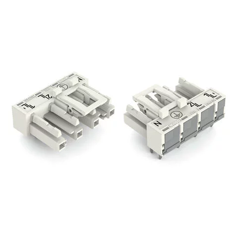
770-824/011-000 - Socket for PCBs; angled; 4-pole; Cod. A; white

  • Brand: Wago
  • Product Code: 770-824/011-000
Description: Female connector/socket WINSTA® MIDI A coding The WINSTA® MIDI female connector/socket A coding offers very secure handling to support drive and control technology tasks. The pluggable PCB connectors with spring pressure connection technology and Push-in CAGE CLAMP® technology from WAGO allow fast, vibration-proof, maintenance-free terminal connections. The color coding and mechanical coding of the pcb connector ensure error-free installation of the individual components – including protection against mismating. The WINSTA® MIDI pcb connector with A coding in white or black is normally used for general mains applications in power distribution. Important parameters in the selection of a pcb connector are the rated current and voltage: They provide information about possible domains of use and applications. This product has a current rating of 25 A – therefore it is suitable for powerful loads. WINSTA® MIDI with Push-in CAGE CLAMP® spring pressure connection technology is used in a broad range of individual products you can use for quick, easy, secure, tailored electrical installation. Lower costs through fast commissioning and elimination of service expenses – solutions from WINSTA® MIDI The WINSTA® Pluggable Connection System is ideally tailored to the very strict requirements of building installation. It makes electrical installation pluggable, and thus more efficient, even more reliable, and error-free. Using this pre-assembled system decreases time spent on assembly and errors during installation at the construction site. Choose quality and durability – the WINSTA® MIDI pcb connector with locking lever from WAGO makes the installation of electrical components substantially easier. effective protection against mismating for automation controllers with A coding for a large number of uses quick replacement of defective units during ongoing operation
  • Available Quantity: 0

$3.04

Electrical data

Note on contact resistance

approx. 1 mΩ of contact resistance

approx. 0.25 mΩ contact transition plug/socket

Connection data

Total number of potentials

4

Number of levels

1

Physical data

Pin spacing

10 mm / 0.394 inches

Width

37 mm / 1.457 inches

Height

18.1 mm / 0.713 inches

Height from the surface

14.6 mm / 0.575 inches

Depth

26 mm / 1.024 inches

Solder pin length

3.5

Solder pin dimensions

1 x 0.8 mm

Drilled hole diameter with tolerance

1.5 (-0.1 … +0.1) mm

Mechanical data

Application

General mains applications

Coding

A

Variable coding

Yes

Marking

N ⏚ 2/L 1/L'

Potential Marking

N ⏚ 2/L 1/L'

Mating force of a plug-in connection

approx. 20 … 70 N (depending on pole number)

Retention force of a plug-in connection

Locked: > 80 N

Unmating force of a plug-in connection

Unlocked: approx. 20 … 70 N (depending on pole number)

Number of mating cycles

200, without resistive load

Design

angled

Plug-in connection

Contact type (pluggable connector)

Female connector/socket

Connector (connection type)

for PCB

Mismating protection

Yes

Note on mismating protection

All WINSTA® components are 100% protected against mismating when:
a.) plugging different numbers of poles
b.) plugging while rotated 180 

c.) plugging while laterally staggered
d.) plugging one pole

Mating direction to the PCB

0

Locking lever

yes

Locking of plug-in connection

locking lever

Note on locking system

All connectors for mounted installations (snap-in versions for lighting fixtures or devices, all types of PCB and distribution connectors) are factory-equipped with locking levers to ensure plugs and sockets are securely locked. Additional locking levers are only required for flying leads (plug/socket).

PCB contact

PCB Contact

THT

Solder pin arrangement

2 in-line solder pins/pole

Number of solder pins per potential

2

Material data

Note (material data)

Information on material data can be found here

Color

white

Insulation material

Polyamide (PA66)

Clamping spring material

Chrome-nickel spring steel (CrNi)

Contact material

Copper or copper alloy; surface-treated

Fire load

0.15

Weight

8.3

Environmental requirements

Processing temperature

-5 … +40 °C

Continuous operating temperature

-35 … +85 °C

Note on continuous operating temperature

Insulating parts for temperatures ≤ 105 °C

CAD data
  • 2D/3D Models 770-824/011-000

    Download
CAE data
  • EPLAN Data Portal 770-824/011-000

    Download
  • ZUKEN Portal 770-824/011-000

    Download
  • EPLAN Data Portal 770-824/011-000

    Download
PCB Design
  • Symbol and Footprint 770-824/011-000

    Download
Compliance Search
  • Environmental Product Compliance 770-824/011-000

    Download