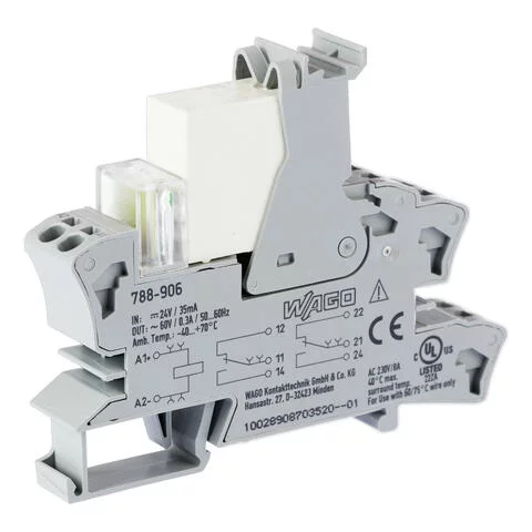
788-906 - Relay module with driven contacts; Nominal input voltage: 24 VDC; 2 changeover contacts; Limiting continuous current: 0.3 A; Green status indicator; Module width: 15 mm
- Brand: Wago
- Product Code: 788-906
Technical data
Control circuit
Nominal input voltage UN | DC 24 V |
Input voltage range | -15 … +10 % |
Nominal input current at UN | 30 mA |
Load circuit
Number of changeover contacts | 2 |
Contact material (relay) | AgNi + Au |
Limiting continuous current | 0.3 A |
Switching voltage (max.) | AC 60 V |
Switching power (resistive) max. | AC 18 VA |
Recommended minimum load | 0.1 V / 1 mA / 1 mW |
Pull-in time (typ.) | 15 |
Drop-out time (typ.) | 12 |
Electrical life (NO; resistive load; 23 °C) | 200 x 103 switching operations |
Mechanical life | 50 x 106 switching operations |
Switching frequency with/without load (max.) | 6 min-1 / 600 min-1 |
Mechanical force-guided operation | Type A |
Signaling
Status indicator | Green LED |
Safety and protection
Rated voltage | 250 |
Rated surge voltage | 4 |
Pollution degree | 2 |
Dielectric strength (control/load circuit) (AC, 1 min) | 4 kVrms |
Dielectric strength (open contact) (AC, 1 min) | 1.5 kVrms |
Dielectric strength (load/load circuit) (AC, 1 min) | 2.5 kVrms |
Safety information 1 |
|
Protection type | IP20 |
Notes
Safety information 1 |
|
Note |
|
Connection data
Connection technology | Push-in CAGE CLAMP® |
Solid conductor | 0.34 … 2.5 mm² / 22 … 14 AWG |
Fine-stranded conductor | 0.34 … 2.5 mm² / 22 … 14 AWG |
Strip length | 9 … 10 mm / 0.35 … 0.39 inch |
Physical data
Width | 15 mm / 0.591 inch |
Height | 86 mm / 3.386 inch |
Depth from upper-edge of DIN-rail | 64 mm / 2.52 inch |
Mechanical data
Mounting type | DIN-35 rail |
Material data
Fire load | 0.675 |
Weight | 50 |
Environmental requirements
Ambient temperature (operation at UN) | -40 … 70 °C |
Ambient temperature UL (operation at UN) | -40 … 40 °C |
Surrounding air temperature (storage) | -40 … +70 °C |
Processing temperature | -25 … +50 °C |
Standards and specifications
Standards/specifications | EN 61010-2-201 EN 61810-1 EN 61810-3 UL 508 (max. 40 °C) |


