Quick Links


Place here any module, widget, design or HTML. for example menu, categories

IIDM

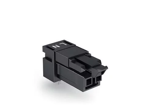
890-802/011-000 - Socket for PCBs; angled; 2-pole; Cod. A; black

  • Brand: Wago
  • Product Code: 890-802/011-000
Description: Female connector/socket WINSTA® MINI with protection against mismating The WINSTA® MINI female connector/socket with locking latch are compact but powerful PCB terminal blocks. They offer convenient operation and the greatest flexibility for installation. Our remarkable number of pluggable PCB connectors with various insertion directions and operating variants offers you the right solution for your application at any time. The mechanical coding and color coding of the pcb connector ensure error-free installation of the individual components – including protection against mismating. Thanks to the color coding and mechanical A coding of WINSTA® MINI pcb connectors, you can clearly distinguish different circuits. Particularly where space is tight, our smallest pluggable connection system, WINSTA® MINI, conveniently displays its advantageous properties. It saves space, and, thanks to Push-in CAGE CLAMP® spring pressure connection technology, it also can be installed quickly, since the installation is low-maintenance and requires no screw connections. WINSTA® MINI solutions for your electrical installation – protected against mismating and maintenance-free The WINSTA® Pluggable Connection System is perfectly tailored to the very strict requirements of building installation. It makes electrical installation pluggable, and therefore more efficient, more reliable, and error-free. Using this pre-assembled system reduces assembly times and installation errors at the construction site. Take advantage of the pluggable version of our maintenance-free spring pressure connection technology too! Plan your installation with WINSTA® MINI pcb connectors with marking from WAGO. effective protection against mismating compact design for conductors with a cross-section up to 1.5 mm² for any mains application fast, secure installation
  • Available Quantity: 0

$2.19

Electrical data

Note on contact resistance

approx. 1 mΩ of contact resistance

approx. 0.25 mΩ contact transition plug/socket

Connection data

Total number of potentials

2

Number of levels

1

Physical data

Pin spacing

4.4 mm / 0.173 inches

Width

10.4 mm / 0.41 inches

Height

15.7 mm / 0.618 inches

Height from the surface

12.2 mm / 0.48 inches

Depth

28.4 mm / 1.118 inches

Solder pin length

3.5

Solder pin dimensions

1 x 0.8 mm

Drilled hole diameter with tolerance

1.3 (+0.1) mm

Mechanical data

Application

General mains applications

Coding

A

Variable coding

No

Marking

L N

Potential Marking

L N

Mating force of a plug-in connection

approx. 20 … 70 N (depending on pole number)

Retention force of a plug-in connection

Locked: > 80 N

Unmating force of a plug-in connection

Unlocked: approx. 20 … 70 N (depending on pole number)

Number of mating cycles

200, without resistive load

Design

angled

Plug-in connection

Contact type (pluggable connector)

Female connector/socket

Connector (connection type)

for PCB

Mismating protection

Yes

Note on mismating protection

All WINSTA® components are 100% protected against mismating when:
a.) plugging different numbers of poles
b.) plugging while rotated 180 

c.) plugging while laterally staggered
d.) plugging one pole

Mating direction to the PCB

0

Locking lever

yes

Locking of plug-in connection

locking lever

Note on locking system

All connectors for mounted installations (snap-in versions for lighting fixtures or devices, all types of PCB and distribution connectors) are factory-equipped with locking levers to ensure plugs and sockets are securely locked. Additional locking levers are only required for flying leads (plug/socket).

PCB contact

PCB Contact

THT

Solder pin arrangement

2 in-line solder pins/pole

Number of solder pins per potential

2

Material data

Note (material data)

Information on material data can be found here

Color

black

Cover color

gray

Insulation material

Polyamide (PA66)

Clamping spring material

Chrome-nickel spring steel (CrNi)

Contact material

Copper or copper alloy; surface-treated

Fire load

0.047

Weight

2.5

Environmental requirements

Processing temperature

-5 … +40 °C

Continuous operating temperature

-35 … +85 °C

Note on continuous operating temperature

Insulating parts for temperatures ≤ 105 °C

CAD data
  • 2D/3D Models 890-802/011-000

    Download
PCB Design
  • Symbol and Footprint 890-802/011-000

    Download
CAE data
  • ZUKEN Portal 890-802/011-000

    Download
Compliance Search
  • Environmental Product Compliance 890-802/011-000

    Download