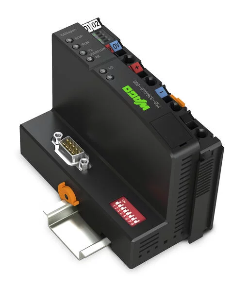
750-338/040-000 - Fieldbus Coupler CANopen; D-Sub; Extreme
- Brand: Wago
- Product Code: 750-338/040-000
Notes
Note | Note: Configuration files required (EDS)! |
Technical data
Communication | CANopen |
Number of fieldbus nodes on master (max.) | 110 |
Baud rate | 10 kBd … 1 MBd |
Bus segment length (max.) | 1000 m |
Transmission medium | Shielded Cu cable 3 x 0.25 mm² |
Number of modules per node (max.) | 64 |
Other CANopen features | NMT slave Minimum boot-up Variable PDO mapping Emergency message Life guarding Empty module configuration |
Number of PDOs | 32 Tx / 32 Rx |
Number of SDOs | 2 SDO servers |
COB ID distribution | SDO, standard |
Node ID distribution | DIP switch |
Communication profile | DS-301 V4.1 |
Device profile | DS-401 V2.0 Limit value monitoring Edge-triggered PDOs Configurable response in the event of an error |
Input and output process image (fieldbus) max. | 512 bytes/512 bytes |
Supply voltage (system) | 24 VDC; via pluggable connector (CAGE CLAMP® connection); Derating must be observed! |
Current consumption (5 V system supply) | 350 |
Total current (system supply) | 1,650 |
Supply voltage (field) | 24 VDC; Power supply via pluggable connector (CAGE CLAMP® connection); Transmission via power jumper contacts; Derating must be observed! |
Input current (typ.) at nominal load (24 V) | 500 |
Power supply efficiency (typ.) at nominal load (24 V) | 90 |
Rated surge voltage | 1 kV |
Number of outgoing power jumper contacts | 2 |
Current carrying capacity (power jumper contacts) | 10 |
Ratings per | IEC/EN 60664-1 |
Derating | Derating (supply voltage): Ambient temperatures under laboratory conditions: (−25 … +30 %); for −40 … +55 °C: 24 V (−25 … +20 %); for +55 … +70 °C: 24 V (−25 … +10 %); Lower limit in all temperature ranges: −27.5 % (including 15 % residual ripple) |
Connection data
Connection technology: communication/fieldbus | CANopen: 1 x D-sub 9 plug |
Connection technology: field supply | 4 x CAGE CLAMP® |
Connection technology: system supply | 2 x CAGE CLAMP® |
Connection technology: device configuration | 1 x Male connector; 4-pole |
Connection type 1 | System/field supply |
Solid conductor | 0.25 … 2.5 mm² / 24 … 14 AWG |
Fine-stranded conductor | 0.25 … 2.5 mm² / 24 … 14 AWG |
Strip length | 8 … 9 mm / 0.31 … 0.35 inches |
Physical data
Width | 50.5 mm / 1.988 inches |
Height | 100 mm / 3.937 inches |
Depth | 71.1 mm / 2.799 inches |
Depth from upper-edge of DIN-rail | 63.9 mm / 2.516 inches |
Mechanical data
Mounting type | DIN-35 rail |
Material data
Color | dark gray |
Housing material | Polycarbonate; polyamide 6.6 |
Fire load | 0.469 |
Weight | 176.5 |
Conformity marking | CE |
Environmental requirements
Ambient temperature (operation) | -40 … +70 °C |
Surrounding air temperature (storage) | -40 … +85 °C |
Protection type | IP20 |
Pollution degree (5) | 2 per IEC 61131-2 |
Operating altitude | without temperature derating: 0 … 2000 m; with temperature derating: 2000 … 5000 m (0.5 K/100 m); 5000 m (max.) |
Mounting position | horizontal (standing/lying); vertical |
Relative humidity (without condensation) | 95 |
Relative humidity (with condensation) | Short-term condensation per Class 3K7/IEC EN 60721-3-3 and E-DIN 40046-721-3 (except for wind-driven precipitation, water and ice formation) |
Vibration resistance | per IEC 60068-2-6 (acceleration: 5g), EN 60870-2-2, IEC 60721-3-1, -3, EN 50155; EN 61373 |
Shock resistance | per IEC 60068-2-27 (15g/11 ms/half-sine/1,000 shocks; 25g/6 ms/1,000 shocks), EN 50155, EN 61373 |
EMC immunity to interference | per EN 61000-6-1, -2, EN 61131-2, marine applications, EN 50121-3-2, -4, -5, EN 60255-26 |
EMC emission of interference | per EN 61000-6-3, -4, EN 61131-2, EN 60255-26, marine applications, EN 60870-2-1, EN 61850-3, EN 50121-3-2, EN 50121-4, -5 |
Exposure to pollutants | Per IEC 60068-2-42 and IEC 60068-2-43 |
Permissible pollutant concentration H2S at a relative humidity < 75% | 10 |
Permissible pollutant concentration SO 2 at a relative humidity < 75% | 25 |


