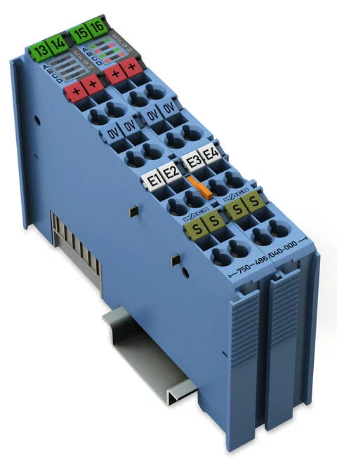
750-486/040-000 - 4-channel analog input; 0/4 … 20 mA; Intrinsically safe; Extreme
- Brand: Wago
- Product Code: 750-486/040-000
- Available Quantity: 0
$1,753.00
Notes
Note | The analog output module must only be operated via 24 VDC Ex i XTR power supply (750-606/040-000)! General information (e.g., installation regulations) on explosion protection is available in the WAGO I/O System 750 XTR manuals! |
Technical data
Number of analog inputs | 4 |
Number of Channels | 4 |
Signal type | Current |
Signal type (current) | 0 … 20 mADC; 4 … 20 mADC; 3.6 … 21 mADC |
Supply voltage (sensor) | 15 VDC; Transmitter supply UV at 20 mA |
Sensor connection | 2 x (3-wire) |
Signal characteristics | Single-ended |
Resolution [bit] | 12 |
Input resistance (max.) | 200 |
Power consumption Pmax. | 2.7 W (at 4 x 21 mA signal current) |
Data width | 4 x 16-bit data; 4 x 8-bit control/status (optional) |
Conversion time (typ. ≤) | 10 |
Measurement error, reference temperature | 25 |
Measurement error, deviation max (upper-range value) ≤± | 0.1 |
Temperature error max. (upper-range value) ≤± | 0.01 |
Intrinsic safety Ex i | yes |
Supply voltage (system) | 5 VDC; via data contacts |
Current consumption (5 V system supply) | 45 |
Supply voltage (field) | 24 VDC; (Ex i XTR power supply: UO = max. 26.8 V); via power jumper contacts (power supply via blade contact; transmission via spring contact) |
Current consumption, field supply (module with no external load) | 19 |
Power loss Pl | 1.5 W (at 4 x 21 mA signal current) |
Isolation | 300 VAC system/field |
Dielectric strength | 510 VAC/775 VDC; per EN 60870-2-1 |
Rated surge voltage | 1 kV; Rated surge voltage between intrinsically safe and non-intrinsically safe circuits: 1.5 kV (EN 60079-11) |
Number of incoming power jumper contacts | 2 |
Number of outgoing power jumper contacts | 2 |
Current carrying capacity (power jumper contacts) | 1 |
Marking | ATEX/IECEx: II 3 (1) G Ex ec [ia Ga] IIC T4 Gc; II (1) D [Ex ia Da] IIIC; I (M1) [Ex ia Ma] I |
Explosion protection
Ex standard | EN/IEC 60079-0, -7, -11 |
Safety-relevant data (circuit) | Uo = 26.8 V; Io = 92.72 mA; Po = 621.27 mW; Linear characteristic curve |
Reactances Ex ia IIC | Lo = 1.6 mH; Co = 0.082 µF |
Reactances Ex ia IIB | Lo = 15 mH; Co = 0.71 µF |
Reactances Ex ia IIA | Lo = 25 mH; Co = 2.36 µF |
Reactances Ex ia I | Lo = 36 mH; Co = 3.84 µF |
Reactances (note) | Reactances without accounting for the concurrence of capacitance (Co) and inductance (Lo) |
Connection data
Connection technology: inputs / outputs | 16 x CAGE CLAMP® |
Connection type 1 | Inputs/Outputs |
Solid conductor | 0.25 … 2.5 mm² / 24 … 14 AWG |
Fine-stranded conductor | 0.25 … 2.5 mm² / 24 … 14 AWG |
Strip length | 8 … 9 mm / 0.31 … 0.35 inches |
Physical data
Width | 24 mm / 0.945 inches |
Height | 100 mm / 3.937 inches |
Depth | 67.8 mm / 2.669 inches |
Depth from upper-edge of DIN-rail | 60.6 mm / 2.386 inches |
Mechanical data
Mounting type | DIN-35 rail |
Material data
Color | blue |
Housing material | Polycarbonate; polyamide 6.6 |
Fire load | 1.247 |
Weight | 96.5 |
Conformity marking | CE |
Environmental requirements
Ambient temperature (operation) | -40 … +70 °C |
Surrounding air temperature (storage) | -40 … +85 °C |
Protection type | IP20 |
Pollution degree (5) | 2 per IEC 61131-2 |
Operating altitude | without temperature derating: 0 … 2000 m; with temperature derating: 2000 … 5000 m (0.5 K/100 m); 5000 m (max.) |
Mounting position | horizontal (standing/lying); vertical |
Relative humidity (without condensation) | 95 |
Relative humidity (with condensation) | Short-term condensation per Class 3K7/IEC EN 60721-3-3 and E-DIN 40046-721-3 (except for wind-driven precipitation, water and ice formation) |
Vibration resistance | per IEC 60068-2-6 (acceleration: 5g), EN 60870-2-2, IEC 60721-3-1, -3 |
Shock resistance | per IEC 60068-2-27 (15g/11 ms/half-sine/1,000 shocks; 25g/6 ms/1,000 shocks), EN 61373 |
EMC immunity to interference | per EN 61000-6-1, -2, EN 61131-2, marine applications, EN 60255-26, EN 60870-2-1, EN 61850-3, IEC 61000-6-5, IEEE 1613, VDEW: 1994 |
EMC emission of interference | per EN 61000-6-3, -4, EN 61131-2, EN 60255-26, marine applications, EN 60870-2-1, EN 61850-3 |
Exposure to pollutants | Per IEC 60068-2-42 and IEC 60068-2-43 |
Permissible pollutant concentration H2S at a relative humidity < 75% | 10 |
Permissible pollutant concentration SO 2 at a relative humidity < 75% | 25 |


