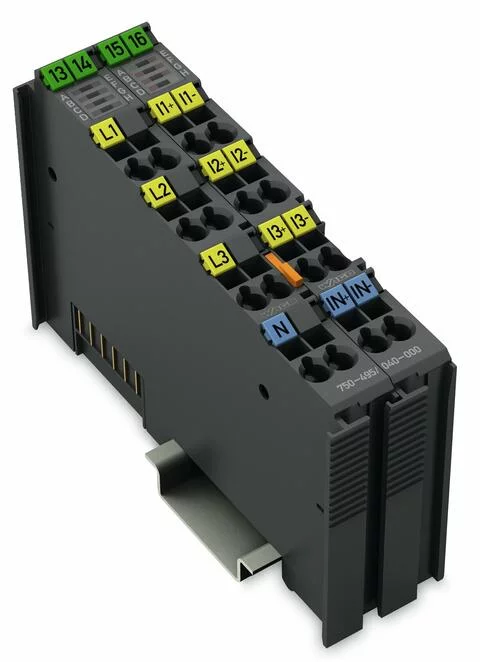
750-495/040-000 - 3-Phase Power Measurement; 690 VAC, 1 A; Extreme
- Brand: Wago
- Product Code: 750-495/040-000
Technical data
Number of measurement inputs | 7 (3 voltage measurement inputs, 4 differential current measurement inputs) |
Signal type | Power measurement |
Signal form | Any periodic signals (considering the threshold frequencies) |
Resolution [bit] | 24 |
Data width | 2 x 128-bit data; 2 x 64-bit control/status |
Voltage path input resistance (typ.) | 1429 |
Current path input resistance (typ.) | 22 mΩ |
Reference for measurement error | AC current/voltage |
Measurement error, reference temperature | 25 |
Measurement error, deviation max (upper-range value) ≤± | 0.5 |
Measurement current (max.) | 1 A |
Measurement cycle time | Adjustable for the arithmetic mean value, min./max. values |
Frequency range (mains frequency) | 45 … 65 Hz |
Frequency range (harmonics analysis) | 0 … 3300 Hz |
Limit frequency | 15.9 |
Rated voltage | ULN = 400 VAC; ULL = 690 VAC |
Calculated values | Line-to-line voltage, power output, energy, power factors, mains frequency, harmonic analysis (up to the 41st harmonic), THD |
Measurement components | Evaluating |
Measurement method | True RMS measurement |
Supply voltage (system) | 5 VDC; via data contacts |
Current consumption (5 V system supply) | 100 |
Dielectric strength | 2.5 kV (AC)/3.5 kV (DC); per EN 60870-2-1 |
Rated surge voltage | 5.0 kV (EN 60870-2-1 / Class VW3); 6.0 kV (UL 508); 6.0 kV (EN 60664-1 / to 4,000 m ASL); 4.0 kV (EN 60664-1 / > 4,000 m to 5,000 m ASL) |
Overvoltage category | Nominal voltage 400 V/690 V in a 3-phase system: III (EN 60664-1 / to 4,000 m ASL); II (EN 60664-1 / > 4,000 m up to 5,000 m ASL) |
Connection data
Connection technology: inputs / outputs | 16 x CAGE CLAMP® |
Connection type 1 | Inputs/Outputs |
Solid conductor | 0.25 … 2.5 mm² / 24 … 14 AWG |
Fine-stranded conductor | 0.25 … 2.5 mm² / 24 … 14 AWG |
Strip length | 8 … 9 mm / 0.31 … 0.35 inch |
Physical data
Width | 24 mm / 0.945 inch |
Height | 100 mm / 3.937 inch |
Depth | 67.8 mm / 2.669 inch |
Depth from upper-edge of DIN-rail | 60.6 mm / 2.386 inch |
Mechanical data
Mounting type | DIN-35 rail |
Material data
Color | dark gray |
Housing material | Polycarbonate; polyamide 6.6 |
Fire load | 0.273 |
Weight | 92.5 |
Conformity marking | CE |
Environmental requirements
Ambient temperature (operation) | -40 … +70 °C |
Surrounding air temperature (storage) | -40 … +85 °C |
Protection type | IP20 |
Pollution degree (5) | 2 per EN 60664-1 |
Operating altitude | without temperature derating: 0 … 2000 m; with temperature derating: 2000 … 5000 m (0.5 K/100 m); 5000 m (max.) |
Mounting position | horizontal (standing/lying); vertical |
Relative humidity (without condensation) | 95 |
Relative humidity (with condensation) | Short-term condensation per Class 3K7/IEC EN 60721-3-3 and E-DIN 40046-721-3 (except for wind-driven precipitation, water and ice formation) |
Vibration resistance | per IEC 60068-2-6 (acceleration: 5g), EN 60870-2-2, IEC 60721-3-1, -3, EN 50155; EN 61373 |
Shock resistance | per IEC 60068-2-27 (15g/11 ms/half-sine/1,000 shocks; 25g/6 ms/1,000 shocks), EN 50155, EN 61373 |
EMC immunity to interference | Per EN 61000-6-1, -2; EN 61131-2; marine applications; EN 50121-3-2; EN 50121-4, -5; EN 60255-26; |
EMC emission of interference | per EN 61000-6-3, -4, EN 61131-2, EN 60255-26, marine applications, EN 60870-2-1, EN 61850-3, EN 50121-3-2, EN 50121-4, -5 |
Exposure to pollutants | Per IEC 60068-2-42 and IEC 60068-2-43 |
Permissible pollutant concentration H2S at a relative humidity < 75% | 10 |
Permissible pollutant concentration SO 2 at a relative humidity < 75% | 25 |


