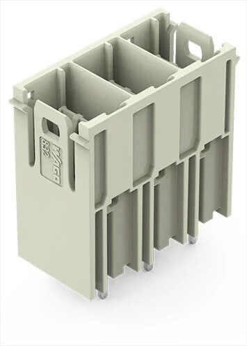
832-3603 - THT male header; 1.2 x 1.2 mm solder pin; straight (90° to PCB); Pin spacing 10.16 mm; 3-pole
- Brand: Wago
- Product Code: 832-3603
Electrical data
IEC Approvals
Ratings per | IEC/EN 60664-1 |
Rated voltage (III / 3) | 800 |
Rated impulse voltage (III/3) | 8 |
Rated voltage (III/2) | 1000 |
Rated impulse voltage (III/2) | 8 |
Nominal voltage (II/2) | 1000 |
Rated surge voltage (II/2) | 8 |
Rated current | 76 |
Legend (ratings) | (III / 2) ≙ Overvoltage category III / Pollution degree 2 |
UL Approvals
Approvals per | UL 1059 |
Rated voltage UL (Use Group B) | 300 |
Rated current UL (Use Group B) | 66 |
Rated voltage UL (Use Group C) | 300 |
Rated current UL (Use Group C) | 66 |
Rated voltage UL (Use Group D) | 600 |
Rated current UL (Use Group D) | 5 |
Ratings per UL
Rated voltage (UL 1977) | 600 |
Rated current UL 1977 | 85 |
CSA Approvals
Approvals per | CSA |
Rated voltage CSA (Use Group B) | 300 |
Rated current CSA (Use Group B) | 66 |
Rated voltage CSA (Use Group C) | 300 |
Rated current CSA (Use Group C) | 66 |
Rated voltage CSA (Use Group D) | 600 |
Rated current CSA (Use Group D) | 5 |
Notes
Safety information 1 | The MCS – MULTI CONNECTION SYSTEM includes connectors without breaking capacity in accordance with DIN EN 61984. When used as intended, these connectors must not be connected/disconnected when live or under load.When used as intended, these connectors must not be connected/disconnected when live or under load. The circuit design should ensure header pins, which can be touched, are not live when unmated. |
Variants: | Other pole numbers Protection against PCB mounting errors Other versions (or variants) can be requested from WAGO Sales or configured at https://configurator.wago.com/. |
Connection data
Total number of potentials | 3 |
Number of connection types | 1 |
Number of levels | 1 |
Physical data
Pin spacing | 10.16 mm / 0.4 inches |
Width | 31.78 mm / 1.251 inches |
Height | 36 mm / 1.417 inches |
Height from the surface | 32 mm / 1.26 inches |
Depth | 16.5 mm / 0.65 inches |
Solder pin length | 4 |
Solder pin dimensions | 1.2 x 1.2 mm |
Drilled hole diameter with tolerance | 1.7 (+0.1) mm |
Mechanical data
Variable coding | Yes |
Plug-in connection
Contact type (pluggable connector) | Male header |
Connector (connection type) | for PCB |
Mismating protection | Yes |
Mating direction to the PCB | 90 |
Locking of plug-in connection | none |
PCB contact
PCB Contact | THT |
Solder pin arrangement | over the entire male connector (in-line) |
Number of solder pins per potential | 3 |
Material data
Note (material data) | |
Color | light gray |
Material group | I |
Insulation material | Polybutylene terephthalate (PBT) |
Flammability class per UL94 | V0 |
Clamping spring material | Chrome-nickel spring steel (CrNi) |
Contact material | Electrolytic copper (ECu) |
Contact plating | Silver |
Weight | 16.3 |
Environmental requirements
Limit temperature range | -60 … +120 °C |


