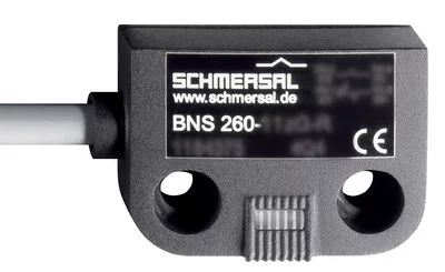
101186155 - BNS 260 STG-AS-R
- Brand: Schmersal
- Product Code: 101186155
- 2 m Pre-wired cable with connector M12, straight, 4-pole
- Safety sensor
- Thermoplastic enclosure
- no mechanical wear
- 36 mm x 26 mm x 13 mm
- Integrated AS-Interface
- Concealed mounting possible
- Long life
- Insensitive to transverse misalignment
- Insensitive to soiling
- AS-Interface LED and status display
Data
Ordering data
Product type description | BNS 260 STG-AS-R |
Article number (order number) | 101186155 |
EAN (European Article Number) | 4030661333656 |
eCl@ss number, version 9.0 | 27-27-24-02 |
eCl@ss number, version 11.0 | 27-27-24-02 |
ETIM number, version 7.0 | EC002544 |
ETIM number, version 6.0 | EC002544 |
Approvals - Standards
Certificates | TÜV cULus ASi-SaW EAC |
General data
Standards | EN 62026-2 EN ISO 13849-1 IEC 60947-5-3 IEC 61508 |
Working principle | Magnetic drive |
Installation conditions (mechanical) | quasi-flush |
Enclosure material | Glass-fibre, reinforced thermoplastic |
Gross weight | 100 g |
Reaction time, maximum | 100 ms |
General data - Features
Coding | Yes |
Integral system diagnostics, status | Yes |
Mechanical data
Actuating element | Magnet |
Door hinge | Right |
Repeat accuracy | ≤ 0.1 x S |
Direction of motion | Head-on to the active surface |
Mechanical data - Switching distances according EN IEC 60947-5-3
Note (Switching distance Sn) | Axial misalignment, a horizontal and vertical misalignment of the safety sensor and the actuator are tolerated. The possible misalignment depends on the distance of the active surfaces of the sensor and the actuator. The sensor remains active within the tolerance range. |
Assured switching distance "ON" S | 5 mm |
Assured switching distance "OFF" S | 15 mm |
Mechanical data - Connection technique
Type of connection | Connecting cable with M12 connector, straight, 4-pole |
Length of cable | 2 m |
Wire cross-section | 0.23 mm |
Wire cross-section | 23 AWG |
Material of the Cable mantle | LSYY |
Mechanical data - Dimensions
Length of sensor | 13 mm |
Height of sensor | 26 mm |
Ambient conditions
Degree of protection | IP67 |
Ambient temperature, minimum | -25 °C |
Ambient temperature, maximum | +60 °C |
Storage and transport temperature, minimum | -25 °C |
Storage and transport temperature, maximum | +70 °C |
Resistance to vibration to EN 60068-2-6 | 10 … 55 Hz, amplitude 1 mm |
Restistance to shock | 30 g / 11 ms |
Protection class | II |
Ambient conditions - Insulation values
Rated insulation voltage U | 32 VDC |
Rated impulse withstand voltage U | 0.8 kV |
Overvoltage category | III |
Degree of pollution to VDE 0100 | 3 |
Electrical data - AS Interface
AS-i Operating voltage, minimum | 18 VDC |
AS-i Operating voltage AS-i maximum | 31.6 VDC |
Note (AS-i Operating voltage) | Protection against polarity reversal |
AS-i Current consumption, maximum | 50 mA |
Electrical data - AS-Interface specification
AS-i Specification | Safety-Slave |
AS-i Version | V 2.1 |
AS-i Profile | S-0.B.F.E |
AS-i, IO-Code | 0x0 |
AS-i, ID-Code | 0xB |
AS-i, ID-Code1 | 0xF |
AS-i, ID-Code2 | 0xE |
AS-i Input, Channel 1 | Data bits DI 0 / DI 1 = dynamic code transmission |
AS-i Input, Channel 2 | Data bits DI 2 / DI 3 = dynamic code transmission |
AS-i Outputs, DO 0 … DO 3 | No Function |
AS-i Parameter bits, P0 ... P3 | No function |
Note (AS-i Parameter bits) | Set the parameter outputs to "1111" (0xF) FID: periphery error |
AS-i Input module address | 0 |
Note (AS-i Input module address) | Preset to address 0, can be changed through AS-interface bus master or hand-held programming device |
Status indication
Note (LED switching conditions display) | (1) LED green: Supply voltage (2) red LED: AS-i communication error / Slave address = 0 |
Pin assignment
PIN 1 | AS-i + |
PIN 2 | n.c. |
PIN 3 | AS-Interface - |
PIN 4 | n.c. |
Scope of delivery
Scope of delivery | Actuators must be ordered separately. |


