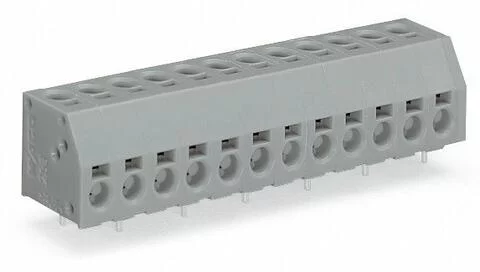
253-102/000-012 - 2-conductor PCB terminal block; 1.5 mm²; Pin spacing 5 mm; 2-pole; PUSH WIRE®; 1,50 mm²; orange
- Brand: Wago
- Product Code: 253-102/000-012
Electrical data
IEC Approvals
Ratings per | IEC/EN 60664-1 |
Rated voltage (III / 3) | 320 |
Rated impulse voltage (III/3) | 4 |
Rated voltage (III/2) | 160 |
Rated impulse voltage (III/2) | 2.5 |
Nominal voltage (II/2) | 320 |
Rated surge voltage (II/2) | 2.5 |
Rated current | 6 |
Legend (ratings) | (III / 2) ≙ Overvoltage category III / Pollution degree 2 |
UL Approvals
Approvals per | UL 1059 |
Rated voltage UL (Use Group B) | 300 |
Rated current UL (Use Group B) | 8 |
Rated voltage UL (Use Group D) | 300 |
Rated current UL (Use Group D) | 8 |
CSA Approvals
Approvals per | CSA |
Rated voltage CSA (Use Group B) | 300 |
Rated current CSA (Use Group B) | 8 |
Rated voltage CSA (Use Group D) | 300 |
Rated current CSA (Use Group D) | 8 |
Notes
Variants: | Other pole numbers Other colors Mixed-color PCB connector strips Direct marking Other versions (or variants) can be requested from WAGO Sales or configured at https://configurator.wago.com/. |
Connection data
Total number of connection points | 4 |
Total number of potentials | 2 |
Number of connection types | 2 |
Number of levels | 2 |
Physical data
Pin spacing | 5 mm / 0.197 inches |
Width | 12 mm / 0.472 inches |
Height | 16.6 mm / 0.654 inches |
Height from the surface | 13 mm / 0.512 inches |
Depth | 12.8 mm / 0.504 inches |
Solder pin length | 3.6 |
Solder pin dimensions | 0.5 x 0.8 mm |
Drilled hole diameter with tolerance | 1.1 (+0.1) mm |
PCB contact
PCB Contact | THT |
Solder pin arrangement | over the entire terminal strip (staggered) |
Number of solder pins per potential | 1 |
Material data
Note (material data) | |
Color | orange |
Material group | I |
Insulation material | Polyamide (PA66) |
Flammability class per UL94 | V0 |
Clamping spring material | Chrome-nickel spring steel (CrNi) |
Contact material | Electrolytic copper (ECu) |
Contact plating | Tin |
Fire load | 0.043 |
Weight | 2 |
Environmental requirements
Limit temperature range | -60 … +105 °C |


