Quick Links


Place here any module, widget, design or HTML. for example menu, categories

IIDM

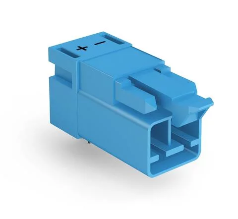
890-3112/011-000 - Plug for PCBs; angled; 2-pole; Cod. I; blue

  • Brand: Wago
  • Product Code: 890-3112/011-000
Description: Male connector/plug WINSTA® MINI with protection against mismating Secure electrical installations with special connection technology: The WINSTA® MINI male connector/plug. The pluggable PCB connectors with spring pressure connection technology and Push-in CAGE CLAMP® technology from WAGO allow impact-resistant, maintenance-free, fast terminal connections. For greater protection in electrical installations, the pcb connector is provided with mechanical protection against mismating. I coding in blue is used to identify WINSTA® MINI pcb connectors, which are used above all in building automation for controlling lighting. Particularly if only limited space is available, our smallest pluggable connection system, WINSTA® MINI, consistently displays its advantages. It saves space, and, thanks to Push-in CAGE CLAMP® spring pressure connection technology, it additionally saves time, since the connection is low-maintenance and can be performed without screw connections. Push-in CAGE CLAMP® spring pressure connection technology – pluggable installation instead of laborious screw connections! The WINSTA® Pluggable Connection System is perfectly tailored to the very strict requirements of building installation. It makes electrical installation pluggable, and consequently more efficient, even more reliable, and error-free. Using this pre-assembled system decreases time spent on assembly and errors during installation at the construction site. Now you can also cut installation expenses without compromising safety and quality: The WINSTA® MINI pcb connector with protection against mismating eliminates the need for servicing and prevents unnecessary downtime. effective protection against mismating consistent IP40 protection with I coding for controlling light (DALI standard) convenient installation and commissioning
  • Available Quantity: 0

$2.21

Electrical data

Note on contact resistance

approx. 1 mΩ of contact resistance

approx. 0.25 mΩ contact transition plug/socket

Connection data

Total number of potentials

2

Number of levels

1

Physical data

Pin spacing

4.4 mm / 0.173 inches

Width

10.4 mm / 0.41 inches

Height

15.7 mm / 0.618 inches

Height from the surface

12.2 mm / 0.48 inches

Depth

28.4 mm / 1.118 inches

Solder pin length

3.5

Solder pin dimensions

1 x 0.8 mm

Drilled hole diameter with tolerance

1.3 (+0.1) mm

Mechanical data

Application

DALI, Lichtmanagement

Coding

I

Variable coding

No

Marking

- +

Potential Marking

- +

Mating force of a plug-in connection

approx. 20 … 70 N (depending on pole number)

Retention force of a plug-in connection

Locked: > 80 N

Unmating force of a plug-in connection

Unlocked: approx. 20 … 70 N (depending on pole number)

Number of mating cycles

200, without resistive load

Design

angled

Plug-in connection

Contact type (pluggable connector)

Male connector/plug

Connector (connection type)

for PCB

Mismating protection

Yes

Note on mismating protection

All WINSTA® components are 100% protected against mismating when:
a.) plugging different numbers of poles
b.) plugging while rotated 180 

c.) plugging while laterally staggered
d.) plugging one pole

Mating direction to the PCB

0

Locking lever

yes

Locking of plug-in connection

locking lever

Note on locking system

All connectors for mounted installations (snap-in versions for lighting fixtures or devices, all types of PCB and distribution connectors) are factory-equipped with locking levers to ensure plugs and sockets are securely locked. Additional locking levers are only required for flying leads (plug/socket).

PCB contact

PCB Contact

THT

Solder pin arrangement

2 in-line solder pins/pole

Number of solder pins per potential

2

Material data

Note (material data)

Information on material data can be found here

Color

blue

Cover color

gray

Insulation material

Polyamide (PA66)

Clamping spring material

Chrome-nickel spring steel (CrNi)

Contact material

Copper or copper alloy; surface-treated

Fire load

0.05

Weight

2.4

Environmental requirements

Processing temperature

-5 … +40 °C

Continuous operating temperature

-35 … +85 °C

Note on continuous operating temperature

Insulating parts for temperatures ≤ 105 °C

CAD data
  • 2D/3D Models 890-3112/011-000

    Download
PCB Design
  • Symbol and Footprint 890-3112/011-000

    Download
CAE data
  • ZUKEN Portal 890-3112/011-000

    Download
Compliance Search
  • Environmental Product Compliance 890-3112/011-000

    Download